estimation method practical it was necessary for the stereo-
scopic images to have the opposite horizontal directions of
those in the
WFV3
and
WFV4
images used in the first experi-
ment. Theoretically, the reference data only needed to cover
a narrow strip across the selected primary
CCD
in the bench-
mark image. Then a dense distribution of
GCPs
was matched
to the reference data of ZY3 (red points in Figure 14). Based
on this process, the installation angles of benchmark image
set 3 and the internal parameters of the primary
CCD
were
calibrated. To determine the installation angles of image sets
1 and 2,
GCPs
for image sets 1 and 2 covering the whole or part
of the selected primary
CCD
images in the cross-track direction
were matched. It was obvious that the greater the cross-track
GCP coverage on the primary
CCD
images, the greater the
absolute constraint on determining the installation angles.
These results are shown in Tables 7 and 8. Although small
Table 6. Relative positioning accuracy (root-mean-square error; pixels) of
WFV3
and
WFV4
cameras.
Location
(Longitude and Latitude)
Imaging Time
WFV3 Accuracy
WFV4 Accuracy
Sample
Line
Plane
Sample
Line
Plane
E108.7_N38.9/E110.9_N38.5 6 Jan 2018
0.501
0.511
0.716
0.496
0.502
0.706
E113.9_N35.6/E116.2_N35.1 4 Feb 2018
0.462
0.481
0.667
0.487
0.582
0.759
E114.3_N34.2/E116.3_N33.8 28 Feb 2018
0.475
0.599
0.764
0.498
0.594
0.775
Table 7. Calibrated parameters of the primary charge-coupled device obtained from the
WFV1
camera.
Installation
Angles
Image Set 1 (°)
Image Set 2 (°)
Image Set 3 (°)
Roll
Pitch
Yaw
Roll
Pitch
Yaw
Roll
Pitch
Yaw
Initial
−24.000 000 0.000 000 0.000 000 −24.000 000 0.000 000 0.000 000 −24.000 000 0.000 000 0.000 000
Calibrated −23.988 157 −0.038 298 −0.199 784 −23.985 717 −0.037 373 −0.193 149 −23.992 785 −0.037 123 −0.193 465
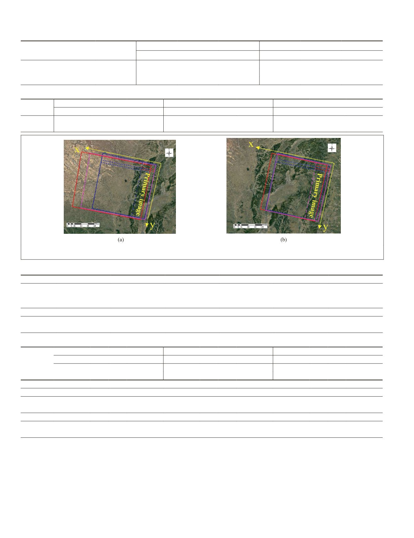
Figure 14. Overlapping relationship of three stereoscopic images. (a) Three stereoscopic images obtained by the
WFV1
camera.
(b) Three stereoscopic images obtained by the
WFV2
camera.
Table 7. Calibrated parameters of the primary charge-coupled device obtained from the
WFV1
camera.
Internal Parameters
a
0
a
1
a
2
a
3
a
4
a
5
Initial
0.000 000e−00
0.000 000e−00
0.000 000e−00
0.000 000e−00
0.000 000e−00
0.000 000e−00
Calibrated
2.326 661e−04
−2.754 595e−08 −6.780 182e−11
6.826 948e−14
−2.653 201e−17
3.524 851e−21
b
0
b
1
b
2
b
3
b
4
b
5
Initial
−1.444 585e−01
2.832
0.000 000e−00
0.000 000e−00
Calibrated −1.480 211e−01
2.627
−1.569 943e−17
9.870 321e−22
Table 8. Calibrated parameters of the primary charge-coupled device obtained from the
WFV2
camera.
Installation
Angles
Image Set 1 (°)
Image Set 2 (°)
Image Set 3 (°)
Roll
Pitch
Yaw
Roll
Pitch
Yaw
Roll
Pitch
Yaw
Initial
−8.000 000 0.000 000 0.000 000 −8.000 000 0.000 000 0.000 000 −8.000 000 0.000 000 0.000 000
Calibrated −8.004 298 −0.027 942 −0.151 749 −8.001 391 −0.027 209 −0.144 021 −8.008 857 −0.026 557 −0.156 557
Internal Parameters
a
0
a
1
a
2
a
3
a
4
a
5
Initial
0.000 000e−00
0.000 000e−00
0.000 000e−00
0.000 000e−00
0.000 000e−00
0.000 000e−00
Calibrated 1.727 234e−04
1.305 699e−08
−8.385 777e−11
6.461 813e−14
−2.187 746e−17
2.687 973e−21
b
0
b
1
b
2
b
3
b
4
b
5
Initial
−1.444 585e−01
2.832 520e−05
0.000 000e−00
0.000 000e−00
0.000 000e−00
0.000 000e−00
Calibrated −1.479 674e−01
2.614 614e−05
−4.086 880e−10 −4.605 832e−15
1.430 961e−17
−1.632 013e−21
824
November 2019
PHOTOGRAMMETRIC ENGINEERING & REMOTE SENSING


