two overlapped images), and the model based on intersection
residual error (using three overlapped images). The section
concludes with the internal-parameter estimation method of
the two self-calibration models.
Flow of the Calibration Approach
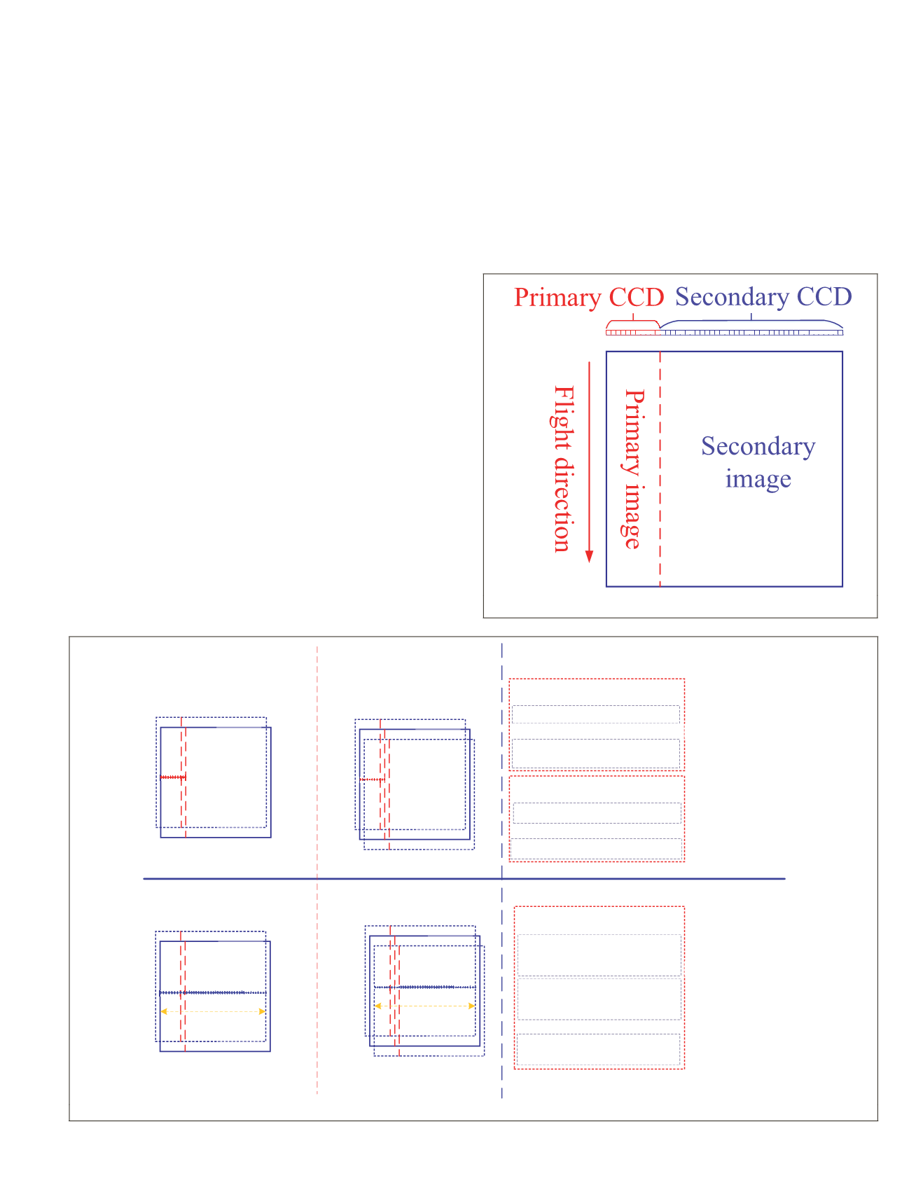
The objective of this article is to reduce the
WFV
cameras’ de-
pendence on the calibration field on the
GF1
satellite. Because
the
CCD
detector on the
WFV
camera has a wide imaging range,
it can be divided into two parts (Figure 3). The primary
CCD
,
which is smaller, should be covered by the calibration field
and calibrated using traditional methods. In order to make
use of the relative geometric constraint for the self-calibration
and then reduce the dependence on ground-based absolute
reference data, two or three stereoscopic images obtained by
the
WFV
camera should be selected. An appropriate overlap-
ping region is necessary for the stereoscopic images, and then
the whole
CCD
detector can be calibrated using the relative
geometric constraint constructed by the tie points and the ac-
curate relative coordinate systems determined by the smaller
primary
CCD
. Using this method, it is possible to minimize
dependence on the absolute calibration reference data.
As can be seen in Figure 4, the basic self-calibration pro-
cess is as follows. First, paired stereoscopic images or three
stereoscopic images with an appropriate overlapping relation-
ship are obtained. One of the stereoscopic images is selected
to be the benchmark image, and traditional methods are used
to calibrate its installation angles and the internal parameters
of its primary
CCD
(Jiang
et al.
2014; Wang
et al.
2014; Wang
et
al.
2017). The matched
GCPs
(red points in Figure 4) from the
reference calibration field are measured across the track. To
ensure that the negative effects of high-frequency attitude er-
rors for the calibration are minimized, uniform distribution of
the
GCPs
in a narrow strip covering the primary
CCD
is neces-
sary (Jiang
et al.
2014; Wang
et al.
2014; Wang
et al.
2016).
Secondly, the installation angles of other stereoscopic im-
ages are calibrated using the
GCPs
matched from the calibra-
tion field and the calibrated primary internal parameters
(Jiang
et al.
2014; Wang
et al.
2014; Wang
et al.
2017). The
matched
GCPs
(red points in Figure 4) should have the same
distribution as the
GCPs
in the first step.
Based on these two steps, the relative spatial relationship
of the stereoscopic images for the subsequent self-calibration
of the whole
CCD
system can be accurately determined based
on the absolute
GCPs
for the primary image and the same
primary internal parameters. The reference camera coor-
dinate system can be determined by the satellite position
Figure 3. Two parts of the single charge-coupled device.
Tie points
Ps
Image 2
Image 3
Image 1
Image 2
Image 3
Overlapping region
Dependency
Step 1
part
1
rimary CCD
GCPs
Image 1
Image 2
Output
Dependency
Step 2
•
GCPs on the primary image part
•
Installation angles of Image 2 and Image 3
Output
Dependency
Step 3
•
For paired stereoscopic images
•
Tie points in the overlapping region
•
reference DEM
•
Internal paramters of the whole CCD
•
For three stereoscopic images
•
Tie points in the overlapping region
Tie points
Image 1
Image 2
Overlapping region
Self-Calibration
model based on
paired stereoscopic
images
Self-Calibration
model based on
three stereoscopic
images
Preprocess
Steps
Based on GCPs
Key Step
Based on tie points
Figure 4. Flow diagram of self-calibration.
PHOTOGRAMMETRIC ENGINEERING & REMOTE SENSING
November 2019
817


