differences remained among the calibrated installation angles
because of the different attitude and orbit measurement errors
or the change in the installation angles, the accurate internal
parameters of the primary
CCD
guaranteed the accuracy of the
relative reference camera coordinate systems. This reflects the
spatial relationship of three stereoscopic images and satisfies
the requirements for self-calibration.
The overlapping relationship of the stereoscopic images
had a direct influence on the required calibration-field cover-
age, and an appropriate overlapping relationship was im-
portant for the effectiveness of the proposed self-calibration
approach. Based on precisely determined relative coordinate
systems, the following self-calibration of the whole
CCD
could
be performed using matched triple overlapping tie points
(blue points in Figure 14). Internal distortion was detected
and compensated based on the intersection residual error
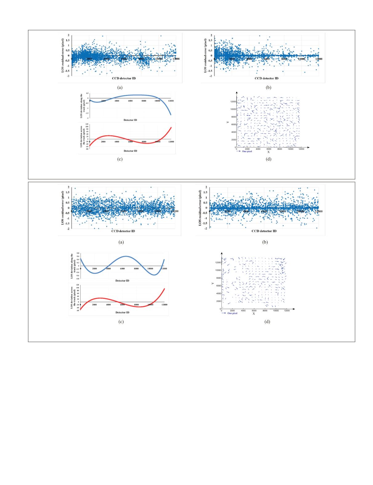
built by the triple overlapping tie points. Figures 15a, 15b,
16a, and 16b show the
LOS
intersection residual error along
and across the track, with no systematic deviation. Figures
15c and 16c show the internal distortion curve of the
WFV1
and
WFV2
whole
CCDs
. The positioning accuracy evaluated
after calibration using high-accuracy reference data of ZY3 is
shown in Figures 15d and 16d; the random plane error vec-
tors showed that the systematic internal distortion of the
WFV1
and
WFV2
cameras was effectively calibrated.
The positioning accuracies of the
WFV1
and
WFV2
cameras
before and after calibration are shown in Table 9. A posi-
tioning error of less than 1.0 pixel was achieved using the
self-calibration approach for three stereoscopic images, again
validating its effectiveness in detecting and compensating
for internal distortion. The self-calibration method based on
a small calibration-field range and the traditional calibration
method based on a large calibration-field range (Jiang
et al.
2014; Wang
et al.
2014) have similar calibration ability.
Figure 15. Calibration results for the
WFV1
camera. (a) Line-of-sight residual error along the track. (b) Line-of-sight residual
error across the track. (c) The internal distortion curve. (d) The positioning residual error vectors after calibration.
Figure 16. Calibration results for the
WFV2
camera. (a) Line-of-sight residual error along the track. (b) Line-of-sight residual
error across the track. (c) The internal distortion curve. (d) The positioning residual error vectors after calibration.
PHOTOGRAMMETRIC ENGINEERING & REMOTE SENSING
November 2019
825


