the
DEM
on the calibrated
LOS
is directly determined by the
topographic conditions. When the terrain is flat, the horizon-
tal inaccuracies in the
DEM
have no obvious influence on the
calibrated
LOS
; however, when the terrain is mountainous, the
influence will become significant. Therefore, the tie points of
the paired stereoscopic images were located within the flat
region to reduce the resolution and accuracy requirements
for the reference
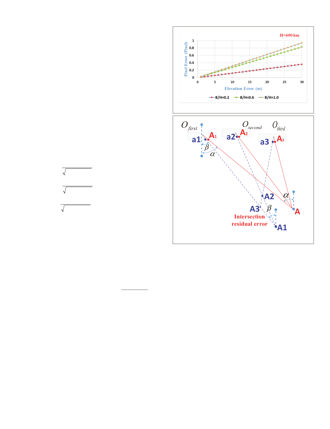
DEM
, and to ensure that all reasonable base-
to-height ratios did not appreciably perturb the
LOS
vector,
which was always less than 1 pixel, as can be seen in Figure
6. The external orbit and attitude measurement errors can be
compensated by the calibrated installation angels according
to their strong correlation relationship (Wang
et al.
2014).
Based on the precisely determined relative camera coordinate
system, the self-calibration model can be constructed as
tan
tan
ψ
ψ λ
x
y
g
R R R
X
1
= ′
body
camera
J2000
body
WGS84
J2000
Y
Z
X
Y
Z
g
g
s
s
s
−
WGS84
WGS84
, (4)
where
X
Y
Z
a
e
B
H B L
a
e
g
g
g
=
−
+
−
WGS84
1
1
2 2
2
sin
cos cos
sin
2
2 2
2
1
1
B
H B L
a
e
B
e H B
+
−
−
(
)
+
cos sin
sin
sin
,
in which the image points (
s
i
,
l
i
)
first
in the first image and (
s
i
,
l
i
)
second
in the second image are matched tie points, and their
corresponding object point
G
i
can be forward-intersected
by them.
R
camera
body
is the installation matrix constructed by the
calibrated camera installation angles. The parameter
e
is the
eccentricity of the Earth;
a
is the semimajor axis of the ellip-
soid;
B
represents the latitude,
L
represe
the height
H
can be extracted from the r
the error equation of the proposed self-c
be constructed as
n
,
(
)
(
)
v s l
U B L
U B L
x y i
x y i i
x y i i
z i i
first second
,
, , ,
,
,
ta
,
,
=
+
(
)
(
)
ψ
(5)
where (
U
x
,
U
y
,
U
z
)
T
represents the right-hand part of Equation
4 and the unknown parameters include the corresponding
ground geodetic coordinates (
B
,
L
)
i
of the matched tie points
and the internal distortion parameters (
a
1
,…,
a
5
,
b
1
,…,
b
5
).
Self-Calibration Model Based on Intersection Residual Error
Based on the analyses with the self-calibration model from
paired stereoscopic images, the reference
DEM
was indispens-
able, and therefore the model is only applicable when the
terrain is flat or a high-accuracy
DEM
is available. Next we
attempted to use three stereoscopic images to compensate the
internal distortion due to the intersection residual error based
on the forward-intersection model of three overlapping tie
points (Cheng
et al.
2018).
As can be seen in Figure 7, three stereoscopic images take
images of object point
A
at the ideal image points
A
1
,
A
2
, and
A
3
when no internal distortion is considered. However, inter-
nal distortion was actually present and was unpredictable,
and object point
A
was actually imaged at image points
a
1
,
a
2
,
f the initial imprecise internal distor-
tersection residual error was probably
-intersection model. Therefore, the
unknown internal distortion resulted in a difference among
the points
A
1
,
A
2
, and
A
3
in object space and the difference
between the
LOS
angles
α
and
β
in image space (Cheng
et al.
2018). When the relative reference camera coordinate systems
were determined accurately, we could make use of the in-
tersection residual error to detect the camera internal distor-
tion. Because of the complete correlation between the camera
installation angles and the internal parameters, the relative
error in the relative camera installation angles would directly
reduce the calibration accuracy of the internal parameters.
Therefore, accurate relative camera installation angles are also
a precondition for the self-calibration model based on inter-
section residual error. Therefore, the unknown parameters in
the self-calibration include the corresponding ground geodet-
ic coordinates in the Earth Cartesian coordinate system of the
matched tie points and the internal distortion parameters.
Based on Equation 1, the self-calibration model based on
intersection residual error can be built as
tan
tan
ψ
ψ λ
x
y
i
R R R
X
1
= ′
body
camera
J2000
body
WGS84
J2000
Y
Z
X
Y
Z
i
i
s
s
s
−
WGS84
WGS84
.(6)
Figure 6. Trend in the pixel error caused by elevation error.
Figure 7. Schematic of the self-calibration based on
intersection residual error.
PHOTOGRAMMETRIC ENGINEERING & REMOTE SENSING
November 2019
819


