and attitude and the camera installation angles. Because the
installation angle is strongly correlated with the attitude and
position error in terms of positioning accuracy, determining
the camera installation angles when the stereoscopic images
were obtained will actually determine their reference camera
coordinate systems.
Finally, based on the self-calibration models, the internal
parameters of the whole
CCD
can be calculated. The tie points
used should be well distributed to maintain consistency
with the
GCPs
in imaging time (blue points in Figure 4). In
this manner, the negative effects of high-frequency attitude
errors can be minimized, and then the accuracy of the relative
spatial relationship can be guaranteed (Jiang
et al.
2014; Wang
et al.
2014; Wang
et al.
2016 ), along with the accuracy of
internal self-calibration.
The internal and external parameters (installation angles)
we used for the linear-array camera on the remote sensing
satellite are completely correlated. The external parameters
are used only to determine the reference camera coordinate
system (Jiang
et al.
2014; Wang
et al.
2014; Cao
et al.
2015;
Cheng
et al.
2017). In the proposed self-calibration method,
the accurate relative reference camera coordinates are neces-
sary; thus, based on the calibration process we designed,
stepwise calibration is necessary and will not influence the
calibration accuracy.
The calibration field should cover the primary
CCD
of the
selected benchmark image in a direction that crosses the
track, and the primary
CCD
of the stereoscopic images should
have an appropriate overlapping relationship. In other words,
the overlapping relationship of the stereoscopic images has
a direct influence on the coverage of the required calibra-
tion field, which guarantees sufficient absolute geometric
constraints for determining the relative reference camera
coordinate systems. An appropriate overlapping relationship
guarantees the accuracy of the calibrated relative camera in-
stallation angles of the stereoscopic images. On this basis, we
use two self-calibration models (Cheng
et al.
2018; Wang
et al.
2018), based on groups of two or three stereoscopic images,
for calibration of the whole
CCD
.
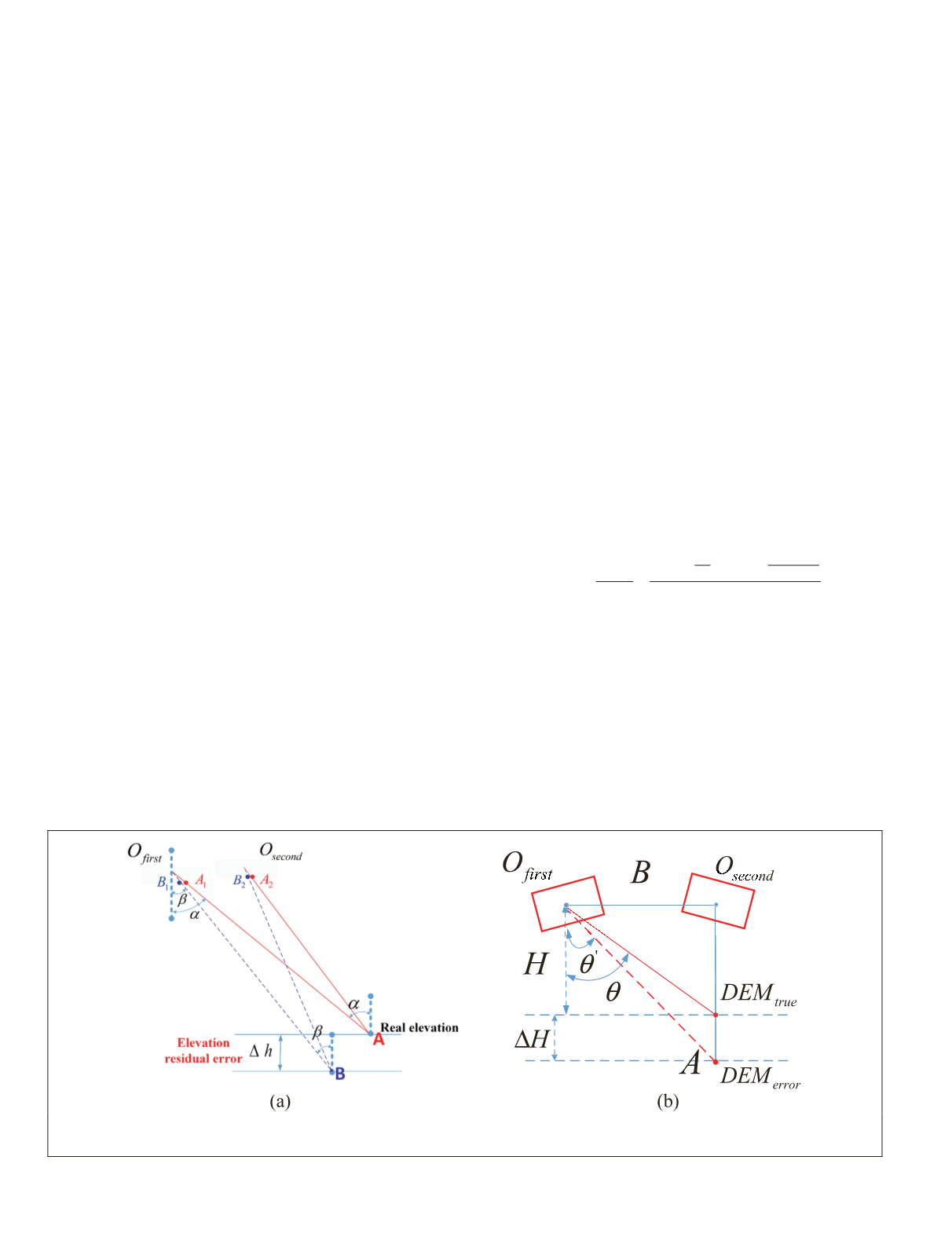
Self-Calibration Model Based on Elevation Residual Error
A forward-intersection model of the satellite image point was
constructed using the ground-reference
the internal distortion of the satellite im
two intersecting
LOSs
via repeated two-v
et al.
2018), using the elevation residual error as shown in
Figure 5.
As can be seen in Figure 5a, under ideal circumstances
the object point
A
forward-intersected by the tie points of
the paired stereoscopic images should be on the real eleva-
tion plane. However, there is an internal distortion, which is
unpredictable, and the object point
A
is actually imaged at
image points
B
1
and
B
2
. Then the
LOSs
of
O
first
B
1
and
O
second
B
1
will be forward-intersected at the updated object point
B
. As
can be seen, the elevation residual error
Δ
h
between
A
and
B
in object space—as well as the
LOS
angle error between
α
and
β
in the image space—is caused by the internal distortion.
Therefore, the internal distortion can be detected based on an
accurate relative reference camera coordinate system (relative
camera installation angles) for the paired stereoscopic images
(Wang
et al.
2018). Because the camera installation angles and
the internal parameters are completely correlated, the eleva-
tion residual error can be caused by the error in relative cam-
era installation angles or the internal distortion. Therefore,
to detect the internal distortion, it is necessary to determine
the accurate relative camera installation angles of the paired
stereoscopic images first; any error in relative camera instal-
lation angles will then directly reduce the calibration accu-
racy of the internal distortion. Because the elevation can be
extracted from the reference
DEM
, the unknown parameters in
the self-calibration include the corresponding ground geo-
detic coordinates (longitude and latitude) of the matched tie
points and the internal distortion parameters.
Figure 5b shows the influence of elevation error
Δ
H
in
object space; the pixel error
Δ
pixel caused in image space can
be calculated by
∆
∆
pixel
pixel
pixel
=
− ′ =
−
+
θ θ
θ
θ
arctan arctan
B
H
B
H H
(3)
in which
θ
pixel
is the angular resolution of each
CCD
detector of
the
WFV
camera on
GF1
,
B
is the imaging baseline, and
H
is the
orbit height of
GF1
. This relationship is shown in Figure 6.
The orbit altitude of
GF1
is about 600 km and the angular
resolution
θ
pixel
is about 5 arcs, so we can see that it has a
relatively small effect on the pixel error. Our aim was to make
the second version of the Advanced Spaceborne Thermal
on Radiometer Global Digital Elevation
2
) appropriate for the self-calibration
tion residual error. This is different from
the influence of the elevation error, which can be intuitively
described. The influence of the horizontal inaccuracies in
Figure 5. Schematic of the self-calibration based on elevation residual error. (a) Elevation residual error caused by internal
distortion; (b) the influence of elevation error.
818
November 2019
PHOTOGRAMMETRIC ENGINEERING & REMOTE SENSING


