maneuvers and ocean range residuals to estimate the system-
atic errors caused by range error and laser pointing error [17].
Magruder adopted a ground-based system including corner
cube retroreflectors and position detectors to accurately verify
the horizontal positions of laser footprint, then the system-
atic error can be evaluated depend on a footprint geolocation
equation [18-19].
Another method on analysis of
LFG
error with mathemati-
cal model for spaceborne laser altimeters are seldom involved
in the scientific literature. Harding mainly investigated the
random error of elevation just using range error model on
the Earth surface [20], but did not establish the error models
of
LFG
in horizontal and vertical components. According to
the model presented by Harding, the root sum square error of
elevation for the
GLAS
is estimated as 13 cm approximately for
the polar ice measurement [21]. Some researchers provided
systematic error models of
LFG
for airborne lidar by resolving
the variations of
LFG
caused by sensor offsets, such as atti-
tude bias, range bias, scanning angle bias [22-23]. However,
it might not be applicable in the analysis of random errors of
LFG
for spaceborne laser altimeter, since the random compo-
nents of sensor errors could not be expressed with constant
biases, but with Root-Mean-Square (
RMS
). Meanwhile, the ef-
fects of terrestrial feature on random errors of
LFG
for airborne
lidar are rarely discussed. Considering that the footprint
size of spaceborne laser altimeter is much larger than that of
airborne lidar, the ground targets within footprint are more
complicated. Therefore, it is necessary to investigate the cor-
responding influence on random errors of
LFG
for spaceborne
laser altimeter.
In this research, we establish a comprehensive mathemati-
cal model of Root-Mean-Square Error (
RMSE
) of
LFG
including
horizontal errors and vertical errors for terrestrial topography
by considering various surface conditions. The contributions
of surface slope and roughness to the random errors of
LFG
are evaluated by using the simulation method for the
GLAS
. To
validate the models in this paper, we introduce a coincident
point cloud collected by an airborne lidar and a waveform
matching method to refine the reference
LFG
. By comparing
the differences between reference
LFG
and original
LFG
pub-
lished by
NSIDC
with computed
RMSEs
of
LFG
, the verification
of the proposed error models is conducted.
The rest of paper is organized as the following: the next
Section thoroughly illustrates the error model of
LFG
followed
by a description of the data set of
GLAS
waveforms and geolo-
cations, lidar data and terrestrial features. The next Section
expounds the simulation and validation results for
LFG
error,
ending with final conclusions.
The Mathematical Model of Laser Footprint Geolocation Error
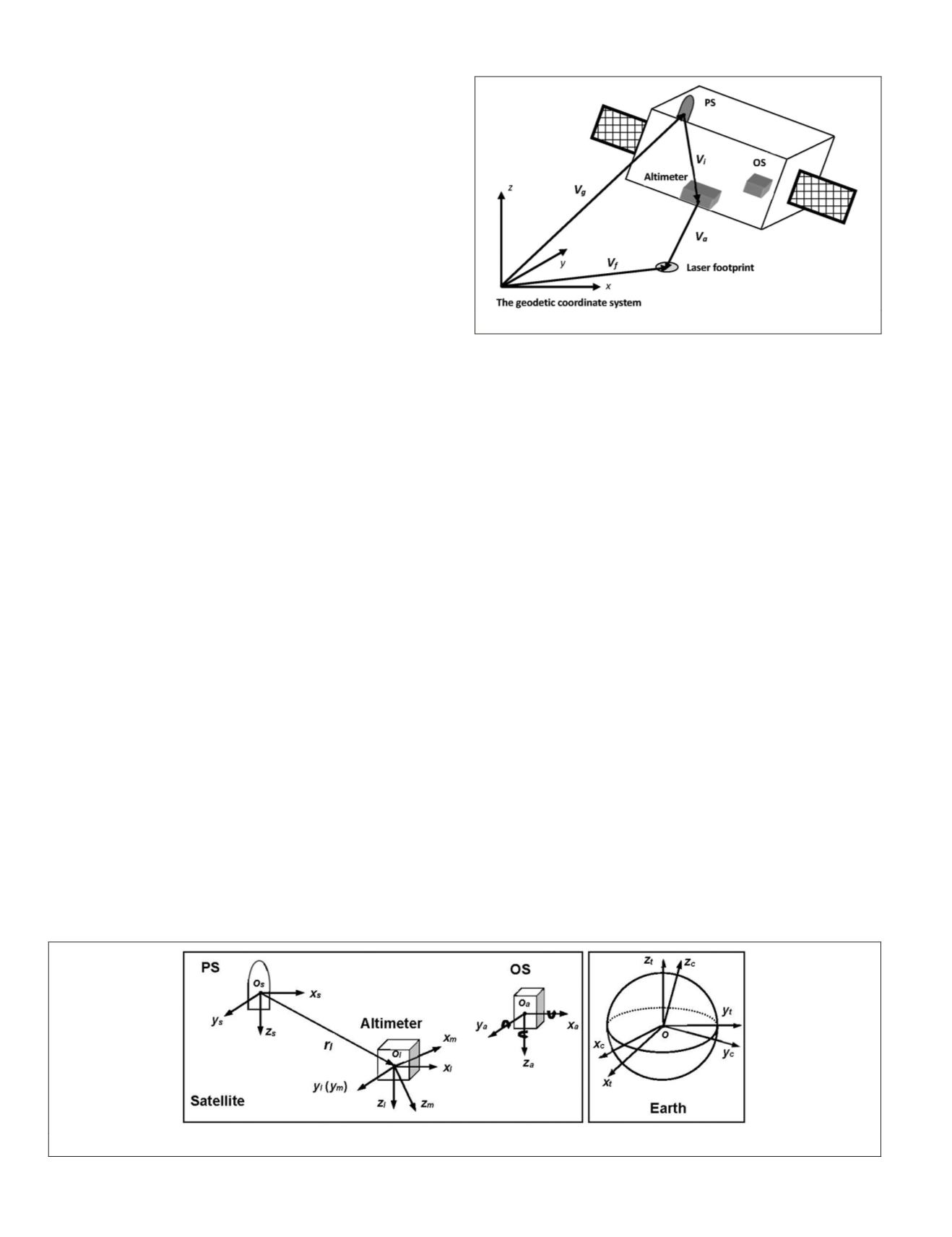
A typical spaceborne laser altimeter system is composed of
three major sensors: laser altimeter, positioning system (
PS
)
and orientation system (OS). The laser altimeter measures the
range from the spaceborne platform to the position within
laser footprint illuminated by the transmitted laser pulse on
the ground. The
PS
and OS provide high-precision position
and attitude information of platform during the measurement
of laser altimeter. The geolocation of laser footprint is deter-
mined by the laser range observation, the laser pointing, the
position and attitude, and the instruments layout. Its geodetic
coordinates can be obtained on the basis of position vector
V
g
, instrument reference vector
V
i
and laser altimeter vector
V
a
as the schematic of laser footprint geolocation described in
Figure 1.
According to the vector addition principle, we provide the ex-
pression of laser footprint geolocation vector
V
f
as the following:
V V V V
f
g
i
a
= + +
(1)
Since the spatial position and orientation of the sensor
during data collection may be given in a local-defined coordi-
nate system, the transformations among the different coordi-
nate systems need to be established through various transla-
tions and rotations as shown below. Six essential coordinate
reference systems are built up in Figure 2: laser pointing
reference system
o
m
-x
m
y
m
z
m
, laser altimeter reference system
o
l
-x
l
y
l
z
l
, positioning reference system
o
s
-x
s
y
s
z
s
, attitude refer-
ence system
o
a
-x
a
y
a
z
a
, celestial reference frame
o-x
c
y
c
z
c
, and
terrestrial reference system
o-x
t
y
t
z
t
, the concrete definitions of
which are presented in the Appendix.
A direct measurement of vector
V
g
is obtained with the
PS
system in the terrestrial reference system, but the vector
V
i
and
V
a
are correspondingly measured in the sensor reference
systems and the celestial reference frame. Based on the defini-
tion of the coordinate reference systems, original
LFG
coordi-
nate in the terrestrial reference system can be described as
V = V + R R R r + R R R R R P
f
g
t c a l
t c a s l m
,
(2)
Figure 2. The six coordinate reference systems relevant to laser footprint geolocation.
Figure 1. The concept of laser footprint geolocation.
648
October 2018
PHOTOGRAMMETRIC ENGINEERING & REMOTE SENSING


