4. Sort the two broken lane points by mileage (
d
i
), and then,
if
d
i
–
d
i
–1
< 0.1 m and
d
i
+1
–
d
i
> 4 m take the adjacent
points of no.
i
and no.
i
+ 1 as the road lane feature points:
d
x X y Y
i
i
S i
S
=
− + −
(
)
⋅
( )
+
( )
tan
tan
α
α
1
2
(4)
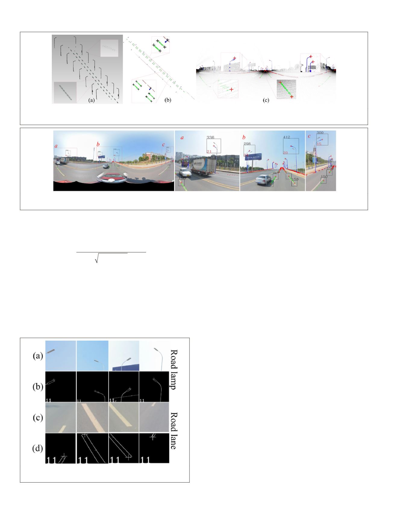
There are 13 704 road lane points and 64 feature points
after filtering. As for road lamps, which are separated and
filtered by clustering, the highest points are taken as road
lamp feature points. There are 9413 road lamp points and 16
feature points after filtering. Figure 6 shows the filtering result
and corresponding feature points of roa
Extraction of Feature Points from Panoramic Im
These 64 road lane and 16 road lamp feature points are pro-
jected onto the panoramic image sequence by initial param-
eters (Zhu 2019), then the projection location is taken as the
center to obtain a local square image window. The window
size is related to the distance between feature points and cam-
era position (
X
S
Y
S
Z
S
). Figure 7 shows the projection result of
the no. 11 panoramic image:
i d
d
d
d
d
x y z
x y z
x y z
x
,
,
,
,
,
,
,
,
,
,
max
Max
=
− − −
(
)
− − +
(
)
− + −
(
)
−
2 2 2
2 2 2
2 2 2
2 2 2
2 2 2
2 2 2
2 2 2
,
,
,
,
,
,
,
,
,
,
,
,
y z
x y z
x y z
x y z
d
d
d
+ +
(
)
+ − −
(
)
+ − +
(
)
+ + −
(
)
d
x y z
+ + +
(
)
2 2 2
300
,
,
,
Road lamps
if
ds
ds
ds
ds
d
<
≤ <
≥
<
20
20
50
50
2
2
150
m
if
m
m
if
m
if
no
Road lanes
max
0
20
m
if
m
no
ds
≥
(5)
where
d
(
x
+
dx
,
y
+
dy
,
z
+
dz
) is the distance between point (
x
+
dx
,
y
+
dy
,
z
+
dz
) and point (
x
,
y
,
z
) in the panoramic image
and
ds
is the distance between (
X
S
Y
S
Z
S
) and point (
x
,
y
,
z
).
As shown in Equation 5, we add ±2 m to the coordinate of
feature point and take 2
d
max
as the window size (
w
), but if
ds
< 20 m,
w
= 300 pixels. For road lanes,
w
= 150. The interval
between adjacent road lamps and lanes gradually decreases
with increasing
ds
; thus, only the feature points of road lamps
(
ds
< 50 m) and lanes (
ds
< 20 m) are used. Then we extract
the edge of objects in the image windows (Canny 1986) and
take the highest (or lowest, shown in Equation 6) edge point
as the feature point. Figure 8a and c shows some lamp and
lane windows in the no. 11 panoramic image, and Figure 8b
and d shows the corresponding feature points:
Figure 6. Road lane, road lamp, and corresponding feature points (the crosses are the feature points). (a) Road lane and lamp
points after filtering. (b) Plane projection of feature points. (c) Panoramic imaging with road lane and lamp points.
Figure 7. The feature points are projected onto the panoramic image. The crosses are the projection location of feature points,
and the upper and lower numbers in the lamp windows express the window size and distance.
Figure 8. Feature point extraction from the image windows.
(a, c) Feature point window. (b, d) Feature point location.
832
November 2019
PHOTOGRAMMETRIC ENGINEERING & REMOTE SENSING


