Extraction of Feature Points from MMS LiDAR Points
Extraction of Road Lamp and Lane Points
Based on existing methods (Cabo
et al.
2016; Serna
et al.
2016; Kumar
et al.
2017; Xu,
et al.
Wang, and Zheng 2017; Ma
et al.
2018; Che and Olsen 2019), we extract road lamp and
lane by horizontal grid and reflectance intensity. First, we di-
vide the grid in the X/Y direction with 15 cm according to the
interval of
MMS
LiDAR
points, then the statistics for minimum
height (
Hmin
), height difference (
Dh
), and number of points
(
Dn
) in each grid, road surface and lamp can be extracted by
these three factors. The road surface is located between two
road curbs, and road lamps are situated on both sides of road
curbs within 5 m; they all rely on road curbs, so the road curb
should be extracted first. Equation 1 indicates the parameters
used in grid extraction, then point height (
z
) was used for
point extraction in each grid, as Equation 2 shows. Figure 4
shows the grid extraction result of road curbs, road lamps,
and road surface:
Grid extraction
Road curb m
Road surfac
: .
0 1
<
Dh
e
Road lamp m
m
:
:
Dn
Dh
>
< <
0
10
15
< 0.4 m and
Dn >
10
(1)
Points extraction
Road curb m
m
Road surf
: .
.
0 05
0 5
< −
<
z Hmin
ace
m
Road lamp
m
:
.
:
.
z Hmin
z Hmin
−
<
−
>
0 05
0 1
(2)
After point extraction, the initial numbers of road surface
and lamp points are 1 961 440 and 9444, respectively, and
then the road lanes are extracted from the road surface by
reflectance intensity. The road surface points with reflectance
intensity larger than 15 are taken as the road lane points.
Figure 5 shows the extraction process.
Noise Point Filtering and Feature Point Extraction
The noise points of road lane and lamp, which affect the
extraction of feature points, must be eliminated. The process
is as follows:
1. Calculate the distances between road lane points and
vehicle trajectory (
s
i
) and then separate two broken road
lanes (land 1: –3 m <
s
i
< 0 m and lane 2: 0 m <
s
i
< 3 m)
on both sides of the vehicle:
s
y Y x X
i
i
S i
S
=
− − −
(
)
⋅
( )
+
( )
tan
tan
α
α
1
2
(3)
where
α
, calculated by vehicle trajectory, is the direction
angle of the road and (
x
i
,
y
i
) are the coordinates of the road
lane points (
i
= 1, 2, …, 28 537).
2. Calculate the median distance of lane 1 and lane 2, namely,
s
′
1
and
s
′
2
, and then filter the noise points away from the two
lanes: (lane 1:|
s
i
–
s
′
1
|< 0.5 m and lane 2: |
s
i
–
s
′
2
|< 0.5 m).
3. Calculate the number of road lane points (
k
) in the neigh-
borhood (less than 0.1 m) and then filter the outlier points
(
k
< 5).
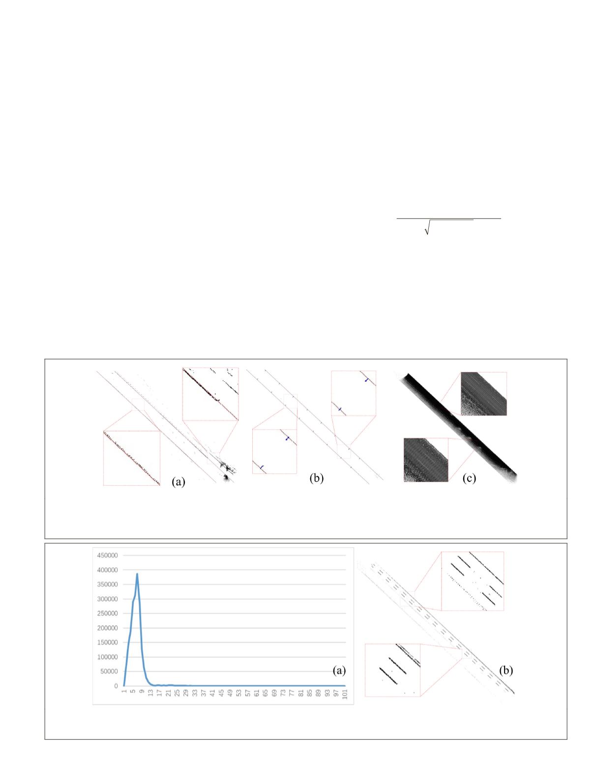
Figure 4. Grid extraction results of road objects. (a) The road curbs and fitting curbs using Hough transformation. Although
there are some extraction errors, the fitting curbs are accurate. (b) The road lamps near the fitting curbs. (c) The road surface
between fitting curbs. The pixel value represents the reflectance intensity, and the intensity of the road lane is higher than
that of other road surfaces.
Figure 5. Extraction of road lanes from the road surface. (a) The intensity distribution of road surface. When the intensity
equals 6, the maximum reaches 386 141; if the intensity is larger than 15, this number is significantly reduced, indicating that
the intensity of road lane is more than 15. (b) The road lane extraction, which include 28 537 points.
PHOTOGRAMMETRIC ENGINEERING & REMOTE SENSING
November 2019
831


