When refocused to the occluded plane, the edge separating
the occluded and unoccluded pixels in the angular patch has
the same orientation as the occlusion edge in the spatial patch
(Figure 3). Moreover, photo-consistency will still hold for the
angular patch in the unoccluded views. However, the single-
occluder model fails in multi-occluder occlusion.
Zhu
et al.
(2017) explored the multi-occluder occlusion
model in the light field and proved the occluder consistency
between the spatial and angular patches for multi-occluder
occlusion. When refocused to the correct depth of the oc-
cluded pixel, the occluded views in the angular patch are the
reprojections of the occluder in the spatial space. The unoc-
cluded views are the corresponding views of the background.
Therefore, the angular patch is similar to the spatial patch
(Figure 4). For more complex multi-occlusion (Figure 5), the
occluder consistency proved correct in that article. The -oc-
cluder consistency for single-occluder occlusion is the special
case of the occluder consistency for multi-occluder occlusion.
The correctness of the occluder consistency in multi-oc-
cluder occlusion is demonstrated on a Mona data set (Wanner,
Meister, and Goldluecke 2013) in Figure 6. As can be seen
from the figure, the angular patch is similar to the spatial
patch. The occluded pixels in the angular patch are the repro-
jection of the occluder in the spatial space.
Depth Estimation
A new depth-estimation method is proposed in this article for
multi-occluder occlusion based on the foregoing occlusion
theory. The flowchart of depth estimation is shown in Figure
7. It consists of the following steps: identifying the occluded
pixels with the center subaperture image; selecting the unoc-
cluded views for the occluded pixels; obtaining the initial
depth by computing the cost volumes in the unoccluded
views; and regularizing the initial depth with an
MRF
.
Occluded-Pixel Identification
In this section, the occluded pixels are effectively identified.
The initial occluded pixels are found by applying Canny edge
detection on the center subaperture image. There are obvious-
ly many unoccluded pixels in the edge obtained. We identify
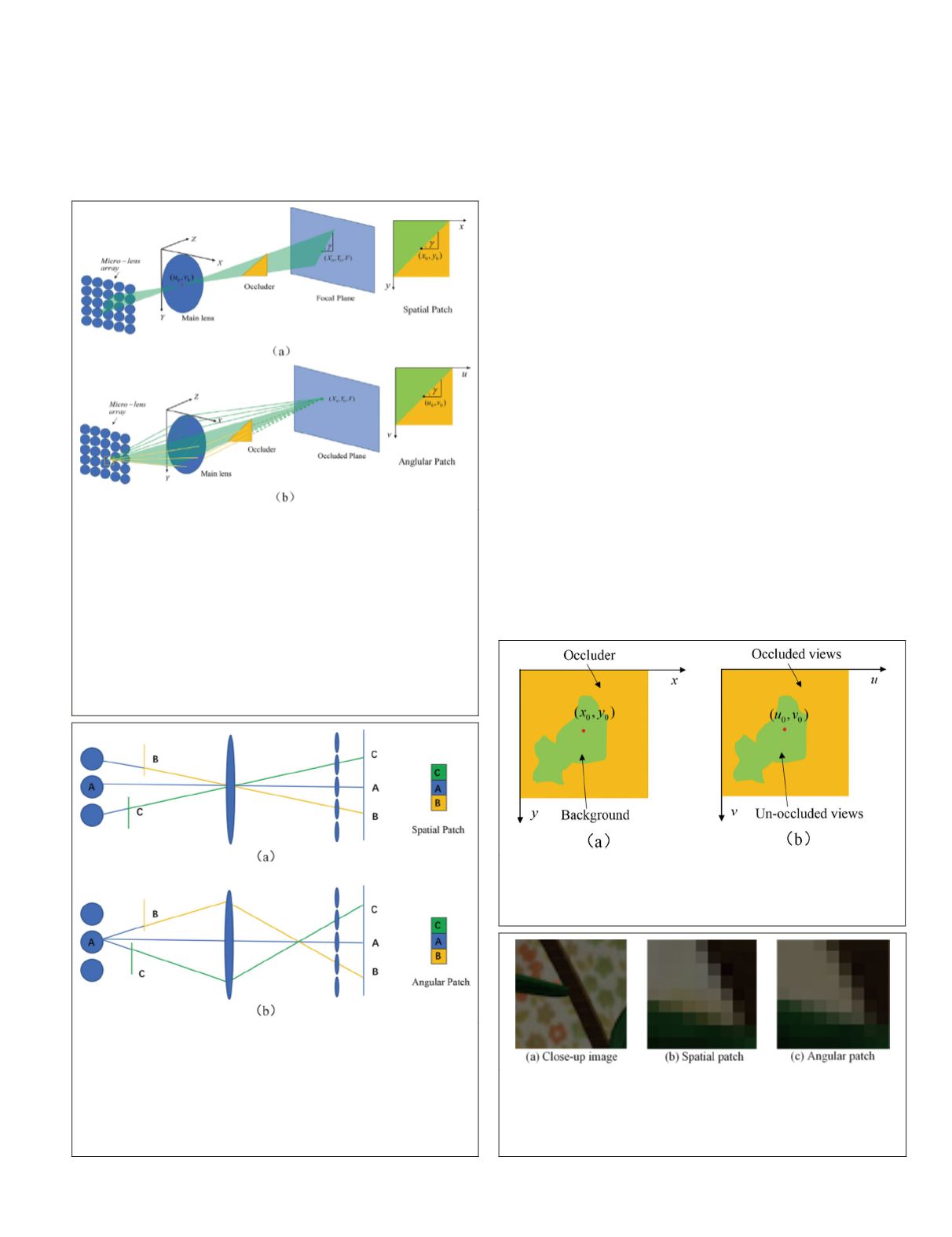
Figure 3. The single-occluder occlusion model of the light
field (T.-C. Wang
et al.
, 2016). The left part of (a) shows
pinhole imaging at the central view (
u
0
,
v
0
). The right
part of (a) shows a spatial patch centered at (
x
0
,
y
0
) in the
center-view image. An occlusion edge on the spatial patch
corresponds to an occluding plane in the 3D space with
orientation
γ
. The left part of (b) shows a refocusing at the
occluded plane. Only the views above the occluder (green
rays) can observe the 3D point
(
X
0
,
Y
0
,
F
); other views are
blocked by the occluder. The right part of (b) shows the
corresponding angular patch of (
x
0
,
y
0
). The orientation of
the edge separating the occluded views (yellow region) and
unoccluded views (green region) in the angular patch is
γ
.
Figure 4. The multi-occluder occlusion model of the light
field. The left part of (a) shows pinhole imaging at the
center view. The right part of (a) shows a spatial patch
(1D) centered at
A
in the center-view image. The left part
of (b) shows a refocusing at object
A
. Only the center view
can observe the object
A
; other views are blocked by the
occluder. The right part of (b) shows the corresponding
angular patch of pixel
A
.
Figure 5. Complex occlusion boundary in (a) spatial patch
and (b) angular patch. The yellow and green areas in (a)
correspond to the occluder and background; in (b), to the
occluded and unoccluded views.
Figure 6. An example of occluder consistency. (a) The close-
up image of the center-view image in the Mona data set.
(b) The spatial patch of the red pixel in (a). (c) The angular
patch corresponding to the red pixel when refocused to the
correct depth.
PHOTOGRAMMETRIC ENGINEERING & REMOTE SENSING
July 2020
445


